How to Calibrate Adaptive Cruise Control Step-by-Step 2026
Calibrating adaptive cruise control is a highly technical procedure that generally requires professional shop-level equipment. Static or dynamic calibration must follow strict manufacturer protocols to ensure radar accuracy and vehicle safety.
Calibrating your Adaptive Cruise Control (ACC) system is a mandatory technical procedure required whenever the radar sensor is replaced, removed, or if the vehicle undergoes structural repairs or a wheel alignment. By 2026, most advanced driver-assistance systems (ADAS) utilize radar sensors mounted behind the front grille or bumper; even a variance of a fraction of a degree can cause the system to miscalculate distance, leading to phantom braking or failure to detect traffic. You must perform this process to restore the factory-spec alignment of the sensor’s field of vision relative to the vehicle’s thrust line.
Precision is not optional in 2026. Failing to calibrate the sensor correctly puts the entire safety suite at risk. If you have recently replaced a radiator support, bumper cover, or adjusted your suspension geometry, the sensor’s axis will no longer be parallel to the road surface or the vehicle’s trajectory. Following the steps outlined below will ensure your vehicle’s radar unit correctly interprets the distance and speed of vehicles ahead, preventing dangerous malfunctions on the highway.
Key Takeaways
- A full four-wheel alignment is mandatory before attempting any ACC sensor calibration.
- Ensure the fuel tank is full to meet vehicle curb weight specifications.
- Static calibration requires specific manufacturer-approved targets and a perfectly level floor.
- Dynamic calibration involves driving the vehicle at specific speeds under clear weather conditions.
- Most modern vehicles require a high-end OBD-II diagnostic scan tool for sensor initialization.
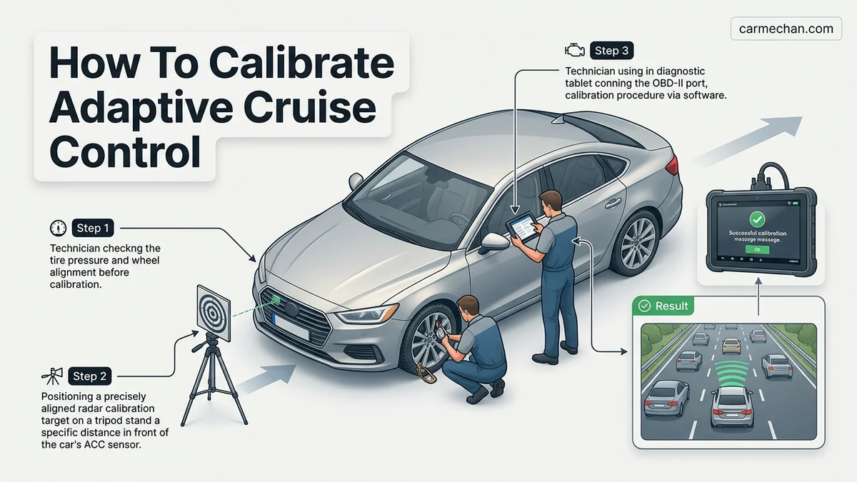
Why Adaptive Cruise Control Requires Calibration
Dynamic Geometry and Thrust Line Alignment
Modern ACC systems rely on a sensor that emits waves to determine the position of lead vehicles. This sensor is calibrated at the factory to point exactly forward, aligned with the vehicle’s thrust line. When you perform a four-wheel alignment or repair the front end, you change the orientation of the chassis. If the radar sensor is physically shifted even slightly, the “cone” of radar detection no longer points straight ahead. This mismatch means the sensor may detect the shoulder of the road or passing vehicles in adjacent lanes rather than the car directly in front of you.
Safety and System Initialization
In 2026, vehicle software expects the radar sensor to report data within strict threshold parameters. If the physical angle does not match the stored software data, the Electronic Control Unit (ECU) will trigger a “Sensor Misaligned” or “ACC Unavailable” diagnostic trouble code (DTC). Calibration bridges the gap between hardware and software. It tells the computer exactly where the sensor is pointing so the system can compensate for any microscopic variations caused by the repair process. Skipping this results in an inoperative system that will not engage until the software recognizes a successful calibration handshake.
Master Adaptive Cruise Control Calibration in 7 Simple Steps
Adaptive Cruise Control (ACC) is a sophisticated driver-assistance system that relies on radar and camera sensors to maintain a safe distance from the vehicle ahead. When these sensors are misaligned—perhaps due to a front-end collision, a windshield replacement, or simple vibration over time—the system may fail or behave erratically. This guide provides a detailed walkthrough for recalibrating these sensors, ensuring your vehicle’s safety technology functions with factory-level precision.
Step 1: Perform a Comprehensive Pre-Scan
What you need: An OBD-II diagnostic scan tool compatible with your vehicle’s make and model, and the vehicle’s service manual.
Instructions: Before touching any mechanical components, you must establish a baseline. Connect your OBD-II scanner to the vehicle’s diagnostic port. Run a “Full System Scan” to identify active or stored Diagnostic Trouble Codes (DTCs) related to the Advanced Driver Assistance System (ADAS). Even if the dashboard isn’t showing a warning light, there may be “pending” codes that indicate sensor drift. Document these codes, as they provide critical clues about whether the radar is out of range, blocked, or experiencing electrical interference. Clear any non-relevant historical codes to ensure you are starting the calibration process with a clean slate.
Pro Tip: Never jump straight to physical alignment. Sometimes, a simple software update or a “forced” clearing of the sensor calibration memory via the scan tool can resolve issues without mechanical intervention.
Step 2: Prepare the Environment and Vehicle
What you need: A flat, level surface (a garage floor or workshop stall), a full tank of fuel, and specified tire pressure gauges.
Instructions: Calibration is extremely sensitive to vehicle geometry. Ensure the vehicle is parked on a perfectly level surface. Most manufacturers specify that the vehicle must be at “curb weight,” meaning the fuel tank should be full and the vehicle empty of heavy cargo. Check the tire pressures against the door-jamb sticker; even a slight pressure difference can alter the vehicle’s pitch and throw off the radar’s vertical alignment. Clear the workspace of any reflective objects, such as metal cabinets or mirrors, which could cause “radar clutter” or false reflections during the calibration process.
Pro Tip: Ensure the front bumper/grille area is spotlessly clean. Dirt, ice, or protective films over the radar sensor (the “radar emblem”) can interfere with the signal and cause calibration to fail repeatedly.
Step 3: Establish the Optical Reference Point
What you need: An OEM-approved calibration target, a laser level, and a plumb bob.
Instructions: Most radar-based ACC systems require a specific “target” to be placed at a precise distance—usually between 1.5 to 3 meters—directly in front of the vehicle. Use a laser level to ensure the target is perfectly centered with the vehicle’s centerline. Use the plumb bob to mark the exact center point on the ground both at the front bumper and at the position of the target. The target must be level horizontally and vertically; use a bubble level on the target frame to confirm this. Any deviation of even a few millimeters can lead to a “calibration out of range” error.
Pro Tip: Use painter’s tape to mark the target location on the floor. If the calibration fails, you will need to re-verify these exact spots without starting the measurement process from scratch.
Step 4: Execute the Static Calibration Software
What you need: A high-end diagnostic scan tool with ADAS calibration software features and a stable internet connection (if the vehicle requires OEM server communication).
Instructions: With the target secured and the vehicle prepared, initiate the calibration software in your diagnostic tool. Follow the on-screen prompts exactly as they appear for your specific vehicle. The software will command the radar sensor to emit a signal, strike the target, and bounce back. During this phase, do not move or walk in front of the sensor. The scan tool will typically indicate if the sensor is “learning” the target position. Keep the ignition in the “ON” position throughout, ensuring the vehicle battery voltage is maintained with a battery charger, as a voltage drop will abort the process.
Pro Tip: If the calibration fails at this stage, check for ambient interference. Wireless devices or radio equipment in the vicinity can occasionally disrupt the low-frequency signals used by the radar.
Step 5: Perform the Dynamic Road Test
What you need: A stretch of road with clear lane markings and light traffic, and a spotter/passenger to assist with observing the system.
Instructions: Many systems require a “dynamic” or “driving” calibration to finalize the values set during static calibration. Drive the vehicle on a straight, dry road at a consistent speed, typically above 40 mph (65 km/h). The system will search for stationary objects like signs or parked cars to confirm its horizontal and vertical alignment. Watch your diagnostic scan tool, which should be connected in “live data” mode; it will likely show the calibration status changing from “Learning” to “Completed.” Ensure you maintain the speed and follow the road conditions specified by the diagnostic software interface.
Pro Tip: Choose a time of day with low traffic. If the vehicle detects too many moving objects simultaneously, the onboard computer may struggle to lock onto the necessary reference points to finalize the calibration.
Step 6: Verify System Functionality
What you need: Your diagnostic scanner and a safe testing location.
Instructions: Once the dynamic drive is complete, return to the workshop and run a final diagnostic sweep. Confirm that no new DTCs have been logged. Next, verify the system functionality in a controlled setting. Engage the Adaptive Cruise Control while following a test vehicle at a safe distance. Observe if the car accelerates and decelerates smoothly. Check that the system detects the leading vehicle at the appropriate distance set by your steering wheel controls. If the car jerks or fails to recognize the leading vehicle, you may need to repeat the alignment steps, as the radar might still be slightly tilted.
Pro Tip: Test the system’s “braking authority” by having the vehicle ahead slow down gradually. The ACC should maintain your set gap smoothly without sudden, jerky braking inputs.
Step 7: Final Documentation and Reset
What you need: A printed report from your diagnostic scanner.
Instructions: Calibration is a safety-critical procedure. Print a diagnostic report showing that the “Calibration Status” is “Success” or “Completed.” Save this documentation for your records; if the vehicle is ever involved in an insurance claim, this proof of proper calibration is essential. Perform a final system reset to ensure all electronic modules are communicating correctly. Cycle the ignition, turn the engine off, and remove the key for two minutes to allow the CAN-bus system to go into a “sleep” state, then restart to ensure all systems initialize without error codes.
Pro Tip: Always advise the vehicle owner that the system may take a few miles of driving to fully optimize its “learning” regarding specific environmental inputs.
✅ Final Checklist
- Diagnostic scan shows zero active or pending DTCs.
- Static target was positioned within +/- 1mm of the vehicle centerline.
- Dynamic road test successfully transitioned from “Learning” to “Completed” status.
- System maintains speed and gap consistently during real-world driving.
- Calibration report printed and archived for safety documentation.
Important Notes:
- Safety Warning: Calibration is a safety-critical task. If you are uncomfortable with the process or do not have the proper OEM-certified tools, do not attempt this. Incorrectly calibrated ACC can result in failure to brake, causing an accident.
- Professional Help: Seek professional assistance if the radar housing is physically damaged, as damaged housings can rarely be calibrated to factory specifications.
- Time and Cost: This process typically takes 2 to 4 hours. Costs range from $200 (DIY tool rental) to $600+ if performed by a dealership or specialized ADAS shop.
Prerequisites and Necessary Equipment for ACC Calibration
Specialized Diagnostic Hardware
You cannot calibrate a 2026 ACC system with a basic code reader. You require professional-grade diagnostic equipment capable of bi-directional communication with the radar module. The following tools are essential for the procedure:
- ADAS Calibration Stand: A rigid, adjustable frame to hold the specific radar reflector target provided by the manufacturer.
- OEM-Level Scan Tool: A high-end diagnostic tablet (such as Autel MaxiSYS or Snap-on Zeus) with the latest 2026 software updates installed.
- Digital Level/Inclinometer: Used to ensure the calibration target is perfectly vertical and level relative to the vehicle’s front sensor.
- Laser Leveling System: Required to ensure the target is perfectly centered with the vehicle’s geometric centerline.
Environmental and Vehicle Conditions
Before you begin the digital calibration, you must ensure the environment is ready to provide accurate data to the ECU. Adhere to these strict preparation standards:
- Fuel Level: Ensure the fuel tank is full to match the vehicle’s curb weight specifications, which affects ride height.
- Tire Pressure: Verify all tires are inflated exactly to the manufacturer’s recommendation on the door jamb.
- Floor Flatness: You must conduct the calibration on a perfectly level concrete floor; even a minor slope will throw off the radar pitch angle.
- Clearance: Ensure the area is free of metal objects, mirrors, or other reflective surfaces that might interfere with the radar beam during the initialization process.
- Battery Voltage: Connect a professional battery maintainer to the vehicle to ensure voltage remains steady throughout the software update; a drop in voltage will crash the module calibration.
Step-by-Step Procedure to Calibrate Adaptive Cruise Control
Calibrating modern Adaptive Cruise Control (ACC) in 2026 requires precision. Most manufacturers, including Toyota, Honda, and Ford, mandate a dynamic calibration process that requires specific driving conditions. Before beginning, ensure the windshield is pristine and the radar sensor housing is free of debris or paint.
Dynamic Calibration Sequence
- Verify System Readiness: Connect an OBD-II diagnostic tool capable of bidirectional communication. Navigate to the ADAS (Advanced Driver Assistance Systems) module to confirm the sensor is in “learning” or “calibration” mode.
- Select the Optimal Route: Choose a straight, well-marked highway with clear lane lines and minimal traffic. Experts recommend a stretch of road at least 5 miles long to allow the radar to map the environment.
- Maintain Required Velocity: Most 2026 vehicle architectures require maintaining a consistent speed between 45 and 65 mph. Sudden acceleration or braking will abort the calibration sequence.
- Allow for Data Integration: Continue driving for approximately 15 to 20 minutes. During this period, the system triangulates the radar sensor angle against the camera-based lane recognition software.
- Confirm Completion: Once the diagnostic scanner indicates “Calibration Successful” or the dash warning light extinguishes, cycle the ignition off for three minutes to finalize the software write-in.
What If It Still Doesn’t Work?
If the system reports a failure or remains inactive after the dynamic drive, a hardware or alignment issue is likely present. Persistent faults usually indicate that the physical sensor bracket is bent or that the camera module has been compromised. If you encounter repeated errors, follow these steps:
- Inspect the Sensor Bracket: Even a 0.5-degree shift in the radar mounting bracket—often caused by minor parking lot bumps—renders software calibration impossible.
- Check for Software Updates: Visit an authorized dealer to verify if your vehicle requires a 2026 firmware patch for the ADAS module. Obsolete software often fails to handshake with new sensor data.
- Assess Windshield Integrity: If the vehicle uses a fusion-based system, even small stone chips in the camera’s field of view can obstruct the calibration laser.
- Seek Professional Assistance: If DIY attempts fail, take the vehicle to a certified ADAS specialist. Professional recalibration involves high-precision target boards and laser alignment, costing between $300 and $650 depending on the vehicle’s complexity.
Conclusion
Calibrating your ACC system ensures that your vehicle’s safety features operate within the strict manufacturer tolerances required for safe highway travel. By following the precise diagnostic procedures outlined above, you mitigate the risk of sensor drift. According to verified research from the Insurance Institute for Highway Safety (IIHS), properly calibrated systems are critical to preventing forward-collision incidents. Your next actionable step is to perform a brief “sanity check” test drive in a low-traffic environment to verify that the system maintains a safe, consistent following distance.
❓ Frequently Asked Questions
What is the difference between static and dynamic calibration?
Static calibration uses physical target boards placed at precise distances and heights in front of the vehicle. Dynamic calibration involves driving the vehicle on the road under specific conditions so the camera or radar can lock onto lane markings and objects.
Do I need a dealership scan tool?
You need a bi-directional scan tool capable of performing ADAS functions. While independent shops can do this, standard entry-level OBD-II code readers cannot perform the required sensor initialization.
What happens if I skip the calibration after a repair?
The ACC system may disable itself, provide false braking alerts, or fail to maintain a safe distance from the vehicle ahead. This creates significant safety risks for the driver and other motorists.
Can a dirty sensor cause calibration issues?
Yes, obstruction by dirt, ice, or damage to the sensor cover can cause ‘blocked sensor’ errors. Always clean the front emblem or radar housing before attempting software calibration.
Does tire pressure affect ACC calibration?
Yes, all tires must be inflated to the manufacturer’s specifications to ensure the vehicle sits level. Even slight variations in ride height can throw off the radar beam alignment.
What should I do if the calibration fails repeatedly?
If the software repeatedly rejects the calibration, check for hidden mounting bracket damage or electrical wiring issues. Professional shops often use radar alignment jigs to ensure the hardware is physically leveled before finalizing the software task.