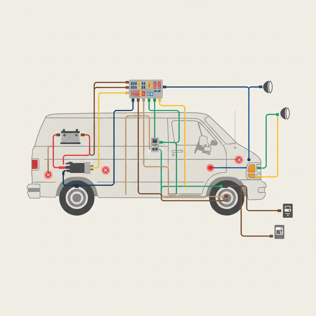
4-Pin Trailer Wiring Diagram: Connect Your Lights Confidently
Last Updated on September 1, 2026 by Ryan
Understanding the standard 4-pin trailer wiring diagram is crucial for safe towing, ensuring your trailer’s lights function correctly. This guide clearly outlines the pin assignments and universal color codes for a hassle-free connection, preventing common electrical issues on the road. Accurate wiring guarantees road safety.
🎯 Key Takeaways


- Identify each 4-pin wire’s function by standard color.
- Ground wire is crucial for all trailer lights to work.
- Check vehicle and trailer sides for matching connections.
- Properly test all light functions before driving.
- Secure all wiring connections to prevent shorts.
Connecting a trailer‘s lights correctly is crucial for both safety and legality. When dealing with the common 4-pin wiring-diagram-recipe.webp” title=”2006 dodge ram trailer wiring diagram recipe.webp“>trailer wiring
system, understanding the specific wire assignments and color codes is paramount. This guide provides you with a clear, focused breakdown of the standard 4-pin trailer wiring diagram, empowering you to confidently identify and connect your trailer lights without guesswork. You’ll learn the universal pin layout, standard wire colors, and the exact function of each connection, ensuring your turn signals, brake lights, and running lights operate perfectly.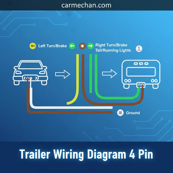
Getting your trailer lights wired correctly isn’t just about avoiding a ticket; it’s about protecting yourself and others on the road. Miswired lights can lead to confusing signals for other drivers, increasing accident risk. By following the standard diagram and understanding each wire’s role, you ensure clear communication of your vehicle’s intentions, making every tow safer. This straightforward system, once understood, makes future connections and troubleshooting a breeze.
Understanding the Standard 4-Pin Connector Layout


The 4-pin trailer connector is the simplest and most widespread wiring setup for basic trailer lighting. It typically handles ground, running lights, and combined brake/turn signals. Knowing its physical layout is the first step in successful wiring.

Identifying the Connector Type and Pin Orientation
You’ll encounter two main components: the male plug on the trailer and the female receptacle on the vehicle. Most users are concerned with wiring the male trailer plug. This plug is usually flat and rectangular, often featuring a small notch or clip on one side. This notch helps ensure correct orientation when plugging into the vehicle. It’s vital to consistently orient the connector to avoid confusion.
For clarity, imagine you are looking directly at the pins of the male trailer plug (the end that inserts into the vehicle’s receptacle). We will describe the pin functions from this perspective. This is the perspective you will typically have when you are physically connecting wires to the back of the plug or checking its pins.
Visualizing the Pin Assignment
While there isn’t a universally numbered “Pin 1, 2, 3, 4” for 4-pin connectors in the same way as higher pin counts, there’s a widely accepted physical arrangement. When looking at the face of the male trailer plug, with the alignment notch (if present) oriented upwards, the pins typically align as follows:
- Top Left Pin: This position usually corresponds to the Left Turn Signal and Brake Light.
- Top Right Pin: This position typically serves the Right Turn Signal and Brake Light.
- Bottom Center Pin (or Bottom Right, depending on specific manufacturer): This is dedicated to the Tail Lights and Running Lights, often referred to as the park lights.
- Bottom Left Pin (often wider or distinct): This crucial connection is always the Ground Wire, completing the circuit for all lights. It often has a slightly different shape or width to help distinguish it.
This layout ensures that when the trailer plug is correctly inserted into the vehicle’s receptacle, each function aligns perfectly, allowing power to flow to the correct lights. Always double-check your specific connector’s physical arrangement against this standard, as minor variations can occur, though the functions remain consistent.
Universal Color Codes and Pin Functions Explained

The beauty of trailer wiring lies in its relatively standardized color coding. While it’s always smart to test, knowing these universal colors makes identifying and connecting wires significantly faster and more accurate.
The Four Essential Wires and Their Standard Colors
Each of the four pins on your trailer connector corresponds to a specific electrical function, and each function is typically represented by a distinct wire color. These colors are recognized across most manufacturers, making them a reliable guide for your wiring project. Here are the standard color codes you will encounter:
- White Wire: This is universally the Ground Wire. It provides the essential return path for electricity, completing the circuit for all other lights. Without a good ground, no other lights will work.
- Brown Wire: This wire powers your Tail Lights, Running Lights, and License Plate Lights. It provides constant power whenever your vehicle’s headlights or parking lights are on.
- Yellow Wire: The yellow wire is dedicated to the Left Turn Signal and Left Brake Light. In a 4-pin system, the brake light and turn signal for each side share the same circuit and bulb.
- Green Wire: Corresponding to the yellow, the green wire handles the Right Turn Signal and Right Brake Light. Like the yellow, it combines both functions for the right side of the trailer.
While these colors are standard, always inspect your existing vehicle wiring if you are tapping into it, as aftermarket installations or unique vehicle models might sometimes deviate. However, for the trailer side, these colors are almost always consistent.
Detailed Functionality of Each Pin
Understanding what each wire does precisely helps with both initial installation and future troubleshooting. Each connection serves a critical purpose in your trailer’s lighting system:
- White Wire (Ground): This is the backbone of your electrical system. It provides a path for current to flow back to the vehicle’s battery. A poor or corroded ground connection is the most common cause of trailer light issues. Ensure this wire has a clean, solid connection to the trailer frame and to the vehicle’s ground system.
- Brown Wire (Tail/Running Lights): This circuit illuminates all non-flashing lights on your trailer. This includes the rear tail lights, side marker lights, and typically the license plate light. These lights come on with your vehicle’s parking lights or headlights, making your trailer visible in low-light conditions.
- Yellow Wire (Left Turn/Brake Light): When you activate your left turn signal or press your brake pedal, power is sent through this wire to the left rear light on your trailer. Since 4-pin systems combine these functions, the same filament in a dual-filament bulb (or the same LED array) serves as both the left turn indicator and the left brake light.
- Green Wire (Right Turn/Brake Light): Identical in function to the yellow wire, this green wire controls the right rear light. It illuminates when you engage your right turn signal or apply the brakes, providing visibility for your right-side intentions.
This combined brake/turn functionality is a hallmark of the 4-pin system, simplifying the wiring by using fewer wires but still providing all essential road signals.
Troubleshooting Common 4-Pin Wiring Glitches
Even with a clear diagram, sometimes your trailer lights decide to play hide-and-seek. Don’t panic! Most 4-pin wiring issues are straightforward to diagnose and fix with a little methodical checking. Understanding common failure points saves you time and frustration.

When Lights Don’t Work: Pinpoint the Problem
If your trailer lights are completely dead or specific functions like turn signals aren’t responding, the issue often boils down to a lack of power or a broken circuit. A simple test light or multimeter is your most valuable tool here.
- No Power at the Vehicle Connector: This is the first place to check. If you’re not getting voltage to the appropriate pins (e.g., green for right turn, yellow for left turn, brown for running lights) when the corresponding function is activated on your tow vehicle, the problem lies with the vehicle’s wiring, a blown fuse, or a faulty converter.
- Loose or Corroded Connections: Often, the simplest explanation is the right one. Vibrations from driving can loosen pins, and moisture can cause corrosion, blocking electrical flow. Visually inspect both the vehicle and trailer connectors for dirt, rust, or bent pins.
- Broken Wires: Wires can get pinched, cut, or frayed, especially where they run along the trailer frame or near moving parts. Carefully trace the wiring path from the connector to each light assembly, looking for visible damage.
Dealing with Flickering or Dim Lights
Flickering or unusually dim lights usually point to an insufficient electrical connection, most commonly a poor ground. A strong, clean ground connection is absolutely critical for all trailer lights to function correctly.
- Poor Ground Connection: The white wire is your ground. If it’s not securely fastened to a clean, bare metal part of the trailer frame, or if the ground point on the vehicle is corroded, you’ll experience problems. Ensure the ground wire connection is free of paint, rust, and dirt.
- Insufficient Power/Voltage Drop: While less common with a simple 4-pin setup unless wiring is very long or very old, sometimes older wiring or a weak vehicle electrical system can lead to voltage drop. However, for 4-pin, a bad ground is almost always the prime suspect for dimming.
- Faulty Light Bulbs or LED Units: Don’t overlook the obvious! Sometimes a bulb is simply old, loose, or has a broken filament. If you’ve ruled out wiring issues, test the bulbs or consider replacing them.
Best Practices for Durable Trailer Wiring Connections
Preventative measures and quality installation are key to avoiding future headaches. Investing a little extra time and using the right materials will significantly extend the life of your trailer’s electrical system, keeping your lights reliable for years to come.
Protecting Your Wires from the Elements
Trailer wiring lives a tough life, exposed to road grime, moisture, UV rays, and physical abrasion. Shielding your wires properly is paramount for longevity.
- Use Wire Loom or Conduit: Running your wires inside flexible plastic wire loom or heavier duty conduit provides excellent physical protection against cuts, abrasions, and impact from road debris.
- Apply Dielectric Grease: For all plug connections, a generous application of dielectric grease (a non-conductive, silicone-based grease) creates a moisture barrier, preventing corrosion and ensuring a good electrical contact.
- Seal Splices and Connections: Any point where wires are joined or connected should be sealed. Heat-shrink tubing with an adhesive liner is an excellent choice for creating a watertight seal around splices and terminals.
- Route Wires Smartly: Avoid routing wires where they can be pinched, rubbed, or exposed to excessive heat (like near exhaust pipes). Use zip ties or clips to secure wiring firmly along the trailer frame, away from moving parts.
Making Secure and Long-Lasting Splices
Improper splices are a common source of intermittent issues and outright failure. While avoiding splices is ideal, sometimes they’re necessary. When you do splice, do it right.
- Crimping with Quality Connectors: If crimping, use high-quality, insulated crimp connectors (like nylon or heat-shrink butt connectors) and a proper ratcheting crimping tool. A good crimp should be mechanically strong and electrically sound. Tug lightly on the wires after crimping to ensure they are secure.
- Soldering for Permanent Connections: For the most robust and permanent connection, soldering is often preferred. After soldering, always insulate the joint thoroughly with heat-shrink tubing to protect it from moisture and physical damage.
- Avoid Twist-and-Tape: Simply twisting wires together and wrapping them in electrical tape is a temporary fix at best. Tape degrades, moisture infiltrates, and the connection will fail. This method should always be avoided for trailer wiring.
- Test as You Go: After making a splice or connection, test the relevant light function before moving on. This helps isolate problems to specific sections of wiring, making troubleshooting much easier.
Conclusion
Understanding your 4-pin trailer wiring diagram isn’t just about getting lights to work; it’s about ensuring safety and compliance on the road. By knowing the function of each wire, you gain the confidence to diagnose issues and make informed decisions about your trailer’s electrical health. Remember, a robust ground connection is key, and preventative measures like proper wire protection and secure splices will save you countless headaches in the long run. Take a few extra moments for inspection and maintenance, and you’ll be well on your way to hassle-free towing. Hit the road with confidence, knowing your lights are shining bright!
❓ Frequently Asked Questions
Why is it important to follow the standard color codes for 4-pin trailer wiring?
Following standard color codes (white for ground, brown for running, yellow for left, green for right) ensures compatibility and simplifies troubleshooting. It allows for consistent connections across different vehicles and trailers, making future repairs or replacements much easier and safer.
What tools are essential for correctly wiring a 4-pin trailer connector?
You’ll primarily need wire strippers, wire crimpers, and a multimeter or test light for verification. Electrical tape or heat shrink tubing is also crucial for insulating connections, ensuring durability and preventing shorts.
How can I test my 4-pin trailer wiring to ensure all lights are working correctly?
After connecting, plug the trailer into the tow vehicle and systematically test each light function: running lights, left turn, right turn, and brakes. Use a helper to observe the lights while you operate them from the vehicle, or use a trailer light tester for a more precise diagnosis without the vehicle.
What are common reasons for 4-pin trailer lights not working after wiring?
Common issues include a poor ground connection, corroded terminals, incorrect wire connections (e.g., swapping left and right signals), blown fuses in the tow vehicle, or a broken wire within the harness. Always start troubleshooting by checking the ground and then the connections for each specific light.
Can I convert a 4-pin wiring system to a 5-pin or 7-pin system?
Yes, you can convert a 4-pin system to a higher pin count system by adding an adapter or by re-wiring the existing harness. This typically involves connecting the existing 4-pin functions and then integrating additional wires for functions like reverse lights, electric brakes, or auxiliary power, depending on the new connector type.
What maintenance is recommended for a 4-pin trailer wiring harness?
Regular maintenance includes checking for corrosion on the pins and inside the connector, inspecting wires for fraying or damage, and ensuring all connections remain secure. Applying dielectric grease to the pins can help prevent corrosion and maintain good electrical contact, extending the lifespan of your wiring.