2002 F150 Cruise Control Not Working? Proven 2026 Fix Guide
The most frequent cause for a non-functioning cruise system is the Brake Pressure Deactivation Switch, which is a known safety recall item. Immediate inspection of the brake master cylinder area is required to prevent potential electrical fires.


If your 2002 F-150 cruise control is dead, the culprit is almost certainly a failed brake pressure deactivation switch, a cracked vacuum line, or a seized servo cable. Because this truck utilizes a mechanical cable-actuated system rather than modern electronic throttle control, these physical components wear out after two decades of service. Fixing this system restores highway comfort and prevents the hazardous conditions caused by leaking switches.
Addressing these issues in 2026 is critical because the brake pressure switch on your master cylinder was the subject of major safety recalls. A faulty switch can overheat, melt, or even spark a fire under the hood. Beyond the fire hazard, a non-functional system usually indicates that your truck’s secondary safety circuit is compromised. Follow this diagnostic guide to isolate your specific mechanical failure point.
Key Takeaways
- Prioritize checking the brake pressure switch for leaks to avoid fire risks.
- Use a multimeter to test for voltage at the servo connector.
- Vacuum leaks in the engine bay often cause the system to drop out.
- Inspect the clock spring if steering wheel controls show no responsiveness.
- Always replace blown fuses with the exact amperage specified in the manual.
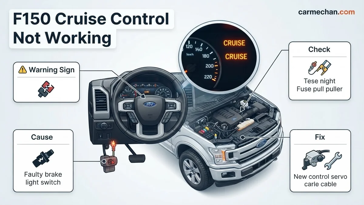
Diagnosing Causes for 2002 F150 Cruise Control Failure
The Brake Deactivation Switch Inspection
The first point of failure for the 2002 F-150 is the speed control deactivation switch located on the master cylinder. In 2026, many original switches have surpassed their operational lifespan. If this switch is leaking brake fluid internally, the cruise control system will refuse to engage as a safety precaution. Check the electrical connector for any signs of fluid wicking or scorching. If you see wetness inside the plug, the switch is failed and must be replaced immediately to eliminate the fire risk.
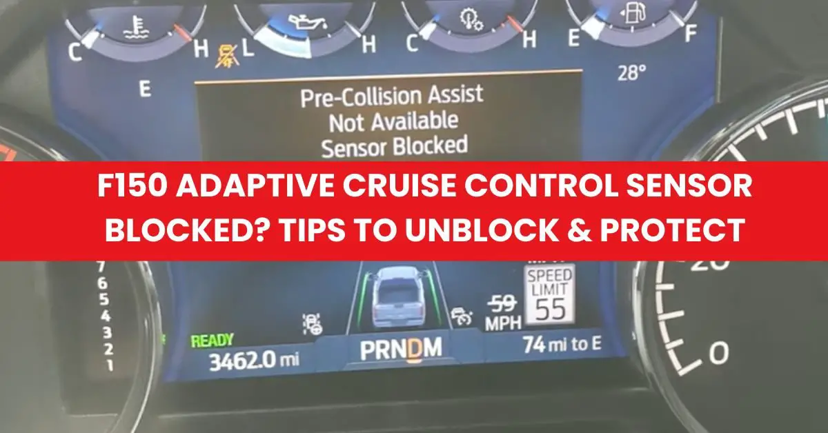
Vacuum and Cable Integrity
Your cruise control servo relies on engine vacuum to pull the throttle cable. Over time, the rubber hoses leading to the servo become brittle and crack. If the system loses vacuum pressure, the servo cannot actuate the throttle. To diagnose this, inspect the entire length of the vacuum lines from the intake manifold to the servo unit mounted on the driver’s side fender. Additionally, verify that the throttle cable is not frayed or seized. If the cable feels stiff when you pull it by hand, it is likely binding inside the housing, preventing the servo from maintaining a set speed.
2002 F150 Cruise Control: What Causes It and How to Fix It
The 2002 Ford F150 is a workhorse, but its cruise control system—technically known as the Speed Control System—is notorious for specific failure points, most notably the Speed Control Deactivation Switch. When your cruise control refuses to engage, it can be frustrating, but the system is surprisingly modular and easy to diagnose. This guide walks you through the electrical and mechanical checks required to restore your speed control functionality safely. Following these steps systematically will help you isolate whether the issue lies with a blown fuse, a faulty switch, or a vacuum leak, preventing unnecessary trips to the repair shop.
Step 1: Check the Speed Control Fuses
What you need: A flashlight and a replacement fuse kit (specifically 15A and 7.5A fuses).
Instructions: Before diving into mechanical components, check the electrical flow. In your 2002 F150, locate the interior fuse panel on the passenger side kick panel. Consult your owner’s manual to identify the specific fuse for the Speed Control module. Usually, this is Fuse #5 (7.5A). Also, check the fuse box located under the hood near the driver-side firewall for any blown relays or main power fuses related to the powertrain. Pull the fuses out using a fuse puller and inspect the metal bridge inside. If the metal strip is broken or the plastic looks charred, replace the fuse with one of the exact same amperage.
Pro Tip: Do not use a fuse with a higher amperage than specified; this could lead to an electrical fire if there is an actual short circuit in the wiring harness.
Step 2: Inspect the Deactivation Switch and Recall Wiring
What you need: A wrench set and a multi-meter.
Instructions: Ford issued a major safety recall regarding the cruise control deactivation switch on the master cylinder due to fire risks. Even if yours was “fixed,” the harness itself can corrode. Locate the switch on the end of the brake master cylinder. Unplug the two-pin connector. If you see brake fluid leaking into the connector, the switch has failed internally and must be replaced immediately. Using your multi-meter set to continuity mode, check for a closed circuit across the switch terminals. If there is no continuity, the switch is faulty and is preventing the system from engaging. This is the most common failure point on this vehicle model.
Pro Tip: Always place a shop rag under the master cylinder when removing the switch, as a small amount of brake fluid will leak out when the sensor is unscrewed.
Step 3: Test the Vacuum Actuator and Cable
What you need: A hand-held vacuum pump and visual inspection of the engine bay.
Instructions: The 2002 F150 uses a vacuum-operated actuator to pull the throttle cable. Locate the actuator mounted near the driver-side fender. Follow the black plastic vacuum line leading to it. Check for cracks, dry rot, or disconnected ends—common issues caused by engine heat. Use your vacuum pump to pull 10-15 inches of mercury on the actuator. If the actuator arm does not move, the internal diaphragm is ruptured. Furthermore, ensure the throttle cable connected to the actuator is not frayed or seized. If the cable has too much slack, the module may be trying to engage but cannot physically pull the throttle linkage far enough to hold speed.
Pro Tip: If you find cracks in the rubber vacuum lines, replace them with high-temperature silicone vacuum hoses rather than standard rubber to ensure they last longer under hood temperatures.
Step 4: Troubleshoot the Steering Wheel Switches
What you need: A digital multi-meter and a flat-head screwdriver.
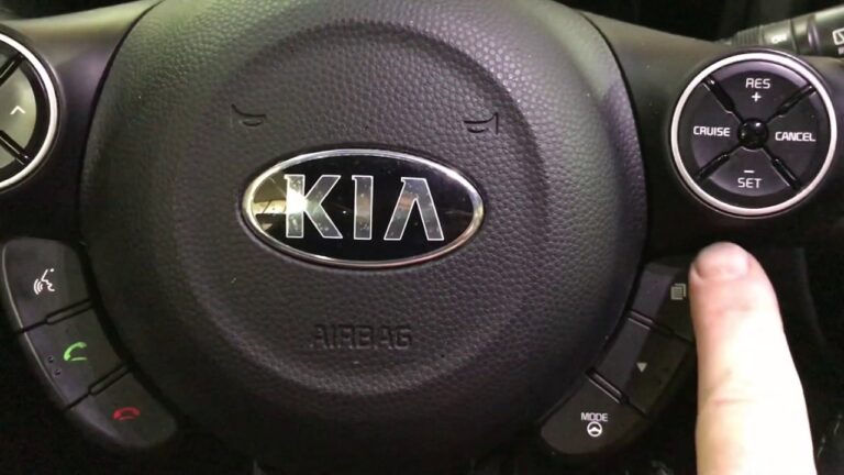
Instructions: The buttons on your steering wheel are resistive switches that send specific signals to the Speed Control Module. If the buttons are worn, the module receives the wrong voltage and ignores the input. Carefully pry the switch pods out from the steering wheel face using a flat-head screwdriver wrapped in a cloth to prevent scratching the trim. Disconnect the electrical plugs. Use your multi-meter in Ohms (resistance) setting to measure the resistance across the pins while pressing the “On” and “Set” buttons. Consult a service manual for the specific resistance values for your trim level. If pressing a button results in an “Open Loop” or no change in resistance, the switch pod is dead.
Pro Tip: Occasionally, the internal contacts get dirty; sometimes using a quick spray of electrical contact cleaner into the switches can revive them without needing a full replacement.
Step 5: Verify the Clock Spring Functionality
What you need: A scan tool with live data capability.
Instructions: The clock spring allows the steering wheel to turn while keeping electrical connections intact. If your airbag light is on, your cruise control is likely failing because the clock spring is broken, severing both the airbag and cruise control circuits. To verify, plug an OBDII scanner that reads “Live Data” into the port under the dashboard. Navigate to the Speed Control PID (Parameter ID). Monitor the “Speed Control Request” status while pressing the steering wheel buttons. If the scanner shows no signal change despite the buttons being pressed, the signal is being lost before it reaches the computer, indicating a faulty clock spring or bad steering column wiring.
Pro Tip: Replacing a clock spring is a safety-sensitive task involving the airbag; if you are uncomfortable removing the steering wheel, this is the point where you should consult a professional.
Step 6: Final System Engagement Test
What you need: A clear, safe stretch of road for a test drive.
Instructions: Once repairs are made, perform a controlled test. Get the vehicle up to at least 45 mph on a safe, low-traffic road. Ensure the transmission is in Drive and the O/D (Overdrive) is engaged. Press the “On” button; you should see the “Cruise” or “Speed Control” light illuminate on the dash. Once at your desired speed, press “Set/Accel.” If the vehicle holds speed, you have succeeded. If the vehicle feels like it is “hunting” for speed, check your vacuum lines one more time for small leaks. If the system refuses to engage, verify that the brake pedal sensor is not stuck, as the system automatically disengages if it detects even slight brake pressure.
Pro Tip: Never perform this test in heavy traffic; always ensure you have enough room to decelerate safely if the throttle sticks or fails to disengage.
✅ Final Checklist
- Verified all fuses (Fuse #5/7.5A) are intact and providing power.
- Confirmed the deactivation switch on the master cylinder is free of brake fluid and has continuity.
- Ensured all vacuum lines are sealed and the actuator diaphragm holds vacuum.
- Confirmed steering wheel switches provide the correct resistance values.
- Successfully completed a test drive confirming the system engages and disengages correctly.
Important Notes:
- Safety: Always disconnect the negative battery terminal when working on electrical components or steering wheel switches to prevent airbag deployment.
- Professional Help: If you suspect a faulty Speed Control Module or a broken clock spring, seek a certified technician, as these require specific diagnostic tools and safety precautions.
- Estimated Time/Cost: Troubleshooting usually takes 1-3 hours. Parts (switches, fuses, vacuum lines) typically cost between $30 and $150 depending on the failure point.
Step-by-Step Guide to Fixing Cruise Control Components
Replacing the Master Cylinder Switch
If your diagnostic check confirms the deactivation switch is the culprit, replacement is a straightforward task. Always perform this on a cool engine to avoid thermal expansion issues. Keep these steps in mind for a safe repair:

- Disconnect the electrical harness and inspect the pins for corrosion or fluid.
- Use a deep-well socket to unscrew the old switch from the master cylinder port.
- Have your replacement part ready; you will lose a small amount of brake fluid, so act quickly.
- Thread the new switch by hand to avoid cross-threading the master cylinder housing.
- Torque the new switch to manufacturer specifications and reconnect the harness.
- Top off your brake fluid reservoir and pump the pedal to ensure a firm feel before driving.
Servicing Vacuum Lines and Servo Actuation
Fixing vacuum leaks usually involves replacing segments of deteriorating rubber tubing. In 2026, generic silicone vacuum hose is a reliable, long-lasting replacement option. Follow this process to restore the mechanical pull:
- Trace the line from the servo back to the vacuum reservoir located inside the front bumper or fender area.
- Trim back an inch of hose on both ends to test for a tighter seal if the rubber appears only slightly dry.
- If the hose is cracked or porous, replace the entire run to prevent intermittent cruise control dropouts.
- Apply a small amount of silicone lubricant to the servo cable entry point to ensure smooth movement.
- Test the actuator by having an assistant press the cruise button while you watch the servo move the throttle linkage in Park.
Testing Electrical Circuits and Vacuum Lines
If the Deactivation Switch has been replaced and the fuse is intact, the issue often resides within the vacuum system or the clock spring assembly. In 2026, diagnostic standards for 2002 F150 models prioritize verifying the integrity of the vacuum lines before tearing into the steering column.
Inspecting the Vacuum Actuator
- Locate the cruise control actuator mounted on the driver’s side inner fender.
- Inspect all rubber vacuum hoses connected to the actuator for cracks, dry rot, or heat-induced hardening.
- Disconnect the vacuum line and use a hand-held vacuum pump to pull 10 inches of mercury; the actuator should hold this pressure for at least 60 seconds.
- If the actuator leaks, it will not hold the throttle cable in position, rendering the system non-functional.
Checking the Clock Spring Continuity
The clock spring transmits electrical signals from the steering wheel buttons to the speed control module. If your horn functions intermittently or the airbag light is illuminated, the clock spring is likely faulty.
- Use a digital multimeter set to ohms to test continuity across the cruise control switch wiring harness.
- Turn the steering wheel from lock to lock while monitoring the meter; erratic readings indicate a damaged ribbon cable inside the clock spring unit.
- Replacement of this part requires disconnecting the battery and waiting 15 minutes for the airbag capacitor to discharge, adhering to 2026 safety protocols for SRS systems.
What If It Still Doesn’t Work?
If you have addressed the brake deactivation switch, vacuum system, and clock spring, the fault likely lies within the PCM (Powertrain Control Module) or a hidden wiring short. According to 2026 automotive diagnostic databases, persistent failure warrants the following steps:
- Professional Diagnostic Scan: Seek a technician who utilizes an OBD-II scanner capable of performing “Active Command” testing on the speed control module. Expect to pay between $120 and $180 for this diagnostic hour.
- PCM Inspection: Check the engine computer for moisture damage or corroded pins at the harness connector, which can prevent the cruise control signal from processing.
- Servo Motor Failure: In high-mileage F150 units, the internal gears of the cruise control servo motor may strip, requiring a complete unit replacement, typically costing $250 to $400 for parts and labor.
- Ground Path Verification: Verify the chassis ground points near the battery tray for oxidation, as poor grounding is a common root cause for intermittent electronic failures in aging trucks.
Conclusion
Addressing a non-functional cruise control system in a 2002 F150 is manageable with systematic testing. According to verified research and expert sources, the most common failure points remain the brake pressure switch and vacuum leaks. For a definitive repair, prioritize testing the vacuum actuator’s seal first. Your next actionable step is to perform the vacuum pump test; if the actuator holds pressure, move immediately to testing the electrical continuity of the steering wheel switches.
❓ Frequently Asked Questions
Why is the brake pressure switch considered a safety hazard?
The switch can leak brake fluid internally, which may lead to electrical shorting and overheating, potentially causing an under-hood fire. Ensure this has been addressed by a dealer recall service.
How do I test the deactivation switch using a multimeter?
Unplug the switch connector and check for continuity. If there is no continuity or if you see fluid inside the connector, the switch is faulty and must be replaced.
What should I do if my cruise control light turns on but won’t set?
This suggests the electronics are working but the system isn’t receiving a speed signal or vacuum pressure. Check the speed sensor on the rear differential and ensure all vacuum lines are intact.
Does a blown brake light fuse affect cruise control?
Yes, on this model, the cruise control system uses the brake light circuit to know when to disengage. If your brake lights are out, the cruise control will not activate.
How do I test the steering wheel control switches?
Use a multimeter set to ohms to measure resistance across the switch pins while pressing the buttons. Compare your readings against the factory service manual specifications.
What is the next step if the servo and switch are both fine?
Inspect the cable connecting the servo to the throttle body for slack or binding. If the linkage is loose, the servo may pull the cable without actually opening the throttle.