
Nissan Factory Radio Wiring Harness Color Codes Explained
Last Updated on May 5, 2026 by Ryan
Navigating the intricate electrical landscape of a modern vehicle can be challenging, especially when upgrading or troubleshooting audio systems. For Nissan owners, deciphering the factory radio wiring harness color codes is a common hurdle, often leading to confusion, incorrect installations, or damage to vehicle electronics if not handled with precision. This comprehensive guide will demystify Nissan’s factory radio wiring harness color codes, providing expert insights into identifying power, ground, speaker, and accessory wires, ensuring a professional and reliable installation or repair every time.

Prime for Young Adults — 6 Months Free
Students and 18–24s get six months of Prime free, then half price.
Start 6 Months FreeWorking on Nissan factory radio wiring? These are the parts installers trust:


As an Amazon Associate we earn from qualifying purchases.
Understanding Nissan Radio Wiring Harness Fundamentals
Recommended Best Deal Products


📤 Share Image
Successfully navigating any automotive electrical project begins with a foundational understanding of the system at hand. For Nissan vehicles, the factory radio wiring harness is a meticulously engineered component, designed to integrate seamlessly with the vehicle’s electrical architecture. These harnesses typically feature a configuration that separates primary power and speaker connections from secondary accessory functions like steering wheel controls or external amplifier triggers. This structured approach, while generally consistent, can vary significantly across model years and trim levels, necessitating a precise and expert approach to identification.
Identifying the correct harness connector types is the initial critical step. While older Nissan models, such as a 2000s Nissan Altima, might feature a more straightforward 16-pin connector for the main radio functions, newer vehicles frequently employ more complex 20-pin or 24-pin harnesses, often with additional dedicated connectors for features like separate amplifier outputs, USB inputs, or display integration. Some premium audio systems, particularly those from Bose or Rockford Fosgate found in models like the Nissan Frontier or Titan, might even utilize proprietary connectors or integrate directly into the vehicle’s CAN-BUS (Controller Area Network) system, making a simple pin-to-pin identification insufficient without proper documentation.
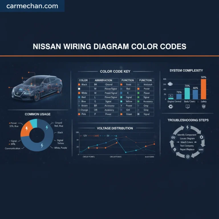
The role of the factory wiring diagram cannot be overstated. While general color code guidelines exist, deviations for specific models, premium audio upgrades, or even regional market variations are not uncommon. A direct comparison against the vehicle’s official service manual or a reliable, vehicle-specific wiring diagram is the most professional and accurate method for verifying color codes and pin assignments. This is particularly crucial when dealing with complex systems where incorrect assumptions can lead to irreversible damage.
Always prioritize safety when working with automotive electrical systems. Before commencing any work, disconnect the vehicle’s negative battery terminal to prevent accidental short circuits or electrical shock. Use only insulated tools designed for electrical work and wear appropriate personal protective equipment. The typical 12V DC power system, while seemingly low voltage, can still deliver significant current, leading to melted wires, blown fuses, or even vehicle fires if mishandled. Factory radio harnesses generally utilize 16-18 AWG wiring for power and ground, and 18-22 AWG for signal and speaker connections; improper wiring can easily compromise these circuits.

Decoding Common Nissan Radio Power, Ground, and Illumination Wire Colors
Understanding the fundamental power, ground, and illumination wires is paramount for any radio installation or troubleshooting. Nissan, like most manufacturers, adheres to generally accepted color coding principles, though variations are certainly possible. A professional installer relies on these consistent patterns as a starting point, always confirming with a multimeter and wiring diagrams for absolute accuracy.

Audible — Listen Free for 30 Days
One free credit a month and thousands of titles included.
Listen Free for 30 DaysConstant 12V Power (Memory)
The constant 12V power wire is essential for maintaining the radio’s memory functions, such as clock settings, radio presets, and CD changer positions, even when the ignition is off. For most Nissan models, this wire is typically Yellow. This circuit remains live at all times, drawing power directly from the battery and usually protected by a 10-15A fuse in the vehicle’s fuse box. Verifying a consistent 12V (or battery voltage, typically 12.6V to 14.4V when the engine is running) on this wire with a multimeter is a critical first step in diagnosis.
Accessory/Switched 12V Power
The accessory or switched 12V power wire is responsible for turning the radio on and off in sync with the vehicle’s ignition. This wire receives power only when the ignition key is in the accessory or “on” position. In many Nissan vehicles, you’ll commonly find this wire colored Red or sometimes Blue/Red. This circuit also typically carries a 10-15A fuse. Incorrectly connecting this wire can lead to the radio remaining on permanently (draining the battery) or failing to power on at all.
Ground Wire
The ground wire is arguably the most critical connection, providing the return path for the electrical circuit. A poor or missing ground connection can cause a myriad of issues, from complete radio failure to intermittent operation, static, or even damage to the unit itself. Nissan, consistent with industry standards, almost universally uses Black for the ground wire. This wire should show continuity to the vehicle’s chassis ground when tested with a multimeter, and it is imperative that this connection is secure and free from corrosion for reliable, quality performance.
Illumination and Dimmer Control
For synchronizing the radio’s display and button lighting with the vehicle’s dashboard illumination, specific wires are dedicated to illumination and dimmer control. Common colors for Nissan in this category include Orange, Orange/White, or Green. The solid Orange wire often provides constant illumination power, while an Orange/White or Green wire might serve as the dimmer control, allowing the radio’s brightness to adjust with the dashboard lights. Proper connection here ensures aesthetic integration and driver comfort during night driving.
Remote Turn-On Wire
When integrating external components like aftermarket amplifiers, power antennas, or certain active subwoofers, a remote turn-on wire is necessary. This wire provides a low-current 12V signal to activate these accessories only when the radio is on. Nissan often designates this function to a Blue or Blue/White wire. It’s crucial not to confuse this with the main accessory power wire, as the remote turn-on is designed for signaling, not direct power delivery to high-current devices.

Nissan Factory Speaker Wiring Color Codes and Polarity Guide
Recommended Best Deal Products


Achieving optimal audio quality hinges significantly on correct speaker wiring, particularly ensuring proper polarity. Miswired speakers can lead to phase cancellation, severely degrading sound staging, bass response, and overall audio fidelity. Nissan, like other manufacturers, employs a consistent color-coding scheme for speaker wires, typically using a solid color for the positive (+) terminal and the same color with a black stripe for the negative (-) terminal.
Standard Speaker Wire Color Pairs for Nissan
While slight variations can occur, the following table represents a highly reliable and trusted guide for typical Nissan factory speaker wiring, seen in models like the Rogue (2014-2020) or Pathfinder (2005-2012):
Understanding Positive and Negative Speaker Wire Polarity
As indicated in the table, the solid colored wire (e.g., White, Gray, Green, Violet) represents the positive terminal (+) for its respective speaker. The same color with a black stripe (e.g., White/Black, Gray/Black) signifies the negative terminal (-). Maintaining this polarity for all speakers is absolutely critical. Reversing the polarity on even one speaker will cause it to move out of phase with the others. When one speaker cone pushes out, the out-of-phase speaker cone pulls in, leading to a cancellation effect, particularly noticeable in lower frequencies. This phase cancellation can reduce bass response by a significant 3dB to 6dB, resulting in a thin, anemic sound that lacks punch and clarity.
Verifying Speaker Polarity
In situations where factory color codes are ambiguous, have been modified by previous installations, or if you suspect an issue, verifying speaker polarity is straightforward. One trusted method involves using a 9V battery. Briefly touch the positive terminal of the battery to one speaker wire and the negative terminal to the other. If the speaker cone visibly moves outward, the wire connected to the battery’s positive terminal is the speaker’s positive wire. If the cone moves inward, the polarity is reversed. For a more sophisticated and precise test, an audio phase tester can be used, which is typically found in a professional installer’s toolkit.
Audible Premium Plus — Annual Membership
12 audiobook credits up front, plus the full Audible catalogue.
See Annual PlansNavigating Aftermarket Radio Installation with Nissan Harness Adapters
Upgrading to an aftermarket head unit in a Nissan vehicle offers enhanced features and superior audio quality, but the installation process demands meticulous attention to wiring. The most professional and reliable approach involves using a vehicle-specific wiring harness adapter, which eliminates the need to cut or splice into the factory wiring. Brands like Metra, Scosche, and PAC offer high-quality adapters designed to seamlessly connect the aftermarket radio’s universal harness to the Nissan’s OEM connector.
Preserves Factory Wiring
Avoids cutting or damaging the vehicle’s original wiring, maintaining resale value and preventing warranty issues.
Simplifies Installation
Makes the process plug-and-play at the vehicle side, reducing installation time and complexity.
Ensures Reliability
Reduces the chance of incorrect connections, short circuits, and poor performance compared to direct splicing.
📋
Step-by-Step Guide: Wiring Aftermarket Harness to Adapter
Recommended Best Deal Products


Lay out both the aftermarket head unit’s harness (which typically follows an ISO standard with colors like Yellow for constant, Red for switched, Black for ground, etc.) and the vehicle-specific adapter harness (e.g., a Metra 70-7550 for a 2010 Nissan Altima). Consult the documentation for both for precise color-to-function mapping.
Connect matching functions between the two harnesses. For example, the Yellow constant 12V wire from the aftermarket radio will connect to the Yellow constant 12V wire on the Metra adapter. Similarly, Red to Red (accessory), Black to Black (ground), and each speaker pair (White to White, White/Black to White/Black, etc.). Pay particular attention to illumination, dimmer, and remote turn-on wires.
For permanent and reliable connections, crimping with high-quality connectors (e.g., butt connectors or quick-disconnects) and a proper crimping tool is highly recommended. For the absolute best connection, soldering and heat shrink tubing provide superior electrical continuity and environmental protection. Avoid simply twisting wires together and taping them, as this creates unreliable and potentially hazardous connections.
Newer Nissan models often employ CAN-BUS systems. For these vehicles, a basic wiring harness adapter may not be sufficient to retain features like steering wheel controls, factory amplifier integration, or R.A.P. (Retained Accessory Power). In such cases, a specialized interface module (e.g., PAC RP4-NI11 for certain Nissan models) is required. This module translates CAN-BUS data into analog signals the aftermarket radio can understand, ensuring all factory features continue to function seamlessly. Connecting these modules requires careful adherence to their specific wiring instructions.
The global market for car audio equipment, valued at over $8 billion in 2021, underscores the immense popularity of aftermarket solutions. Achieving a professional-grade installation relies on both accurate wiring and robust connections. For instance, using a high-quality crimping tool can achieve pull-out strength exceeding 50 lbs, providing a connection that will endure the vibrations and temperature fluctuations of a vehicle’s environment. This commitment to quality ensures a reliable and long-lasting audio upgrade.
Troubleshooting Common Nissan Radio Wiring Issues and Best Practices
Even with the most comprehensive guide, wiring issues can occasionally arise. Knowing how to systematically diagnose and resolve common problems is a hallmark of an expert installer. Approximately 30% of aftermarket installation issues are attributed to incorrect wiring or poor connections, highlighting the importance of robust troubleshooting skills.
Diagnosing No-Power Situations
If an aftermarket radio fails to power on in a Nissan, the first steps involve checking the power supply. Begin by verifying the relevant fuses, both in the vehicle’s fuse box (e.g., the F-8 “Radio” fuse in the IPDM E/R – Intelligent Power Distribution Module Engine Room – for a 2015 Nissan Rogue) and any inline fuses supplied with the aftermarket radio. Next, use a digital multimeter to check for 12V at the constant (Yellow) and accessory/switched (Red) power wires. No voltage on the Yellow wire indicates a blown fuse or a break in the constant power circuit. If there’s 12V on Yellow but not Red when the ignition is on, the accessory circuit is compromised.
Troubleshooting No-Sound Issues
A radio that powers on but produces no sound often points to speaker or amplifier issues. Verify all speaker wire connections are secure and correctly polarized. Ensure the amplifier (if present, factory or aftermarket) is receiving its remote turn-on signal (typically Blue or Blue/White wire) and adequate power. Check the radio’s fader and balance settings to ensure they haven’t been inadvertently set to an extreme. A common oversight is forgetting to connect the remote turn-on wire to an aftermarket amplifier, which will prevent it from powering on.
Resolving Intermittent Power or Noise Issues
Intermittent power, static, or whining noises (especially those that increase with engine RPM) are frequently attributed to a poor ground connection. A faulty ground can introduce electrical resistance, causing voltage drops of 0.5V or more, leading to unstable operation. Ensure the ground wire is securely fastened to a clean, unpainted metal surface on the vehicle chassis. Also, inspect all connections for proper insulation integrity; exposed wires can short circuit and cause noise. Proper wire routing, away from high-voltage cables or engine components, is also a best practice to mitigate induced noise.
Addressing Steering Wheel Control Malfunction
If steering wheel controls cease to function after an aftermarket radio installation, the issue almost invariably lies with the steering wheel control interface module or its connections. Double-check that the interface module is correctly wired according to its specific instructions. Many modules require a specific programming sequence for the vehicle, which might need to be repeated. Ensure the data wires (often a specific pair of wires on the Nissan harness that carry the steering wheel control signals) are securely connected to the interface module.
Before reassembling the dashboard, conduct a full functional test of the new radio, including all speakers, tuner, CD/USB/Bluetooth playback, and any retained factory features like steering wheel controls. This proactive step can save considerable time and effort by allowing you to address any issues while components are still accessible.
A comprehensive, quality installation relies not just on initial correct wiring but also on meticulous testing and robust troubleshooting. These best practices ensure a trusted, reliable, and professional outcome for any Nissan radio upgrade or repair.
Conclusion
Accurate identification of Nissan radio wiring harness colors is paramount for successful installations, whether replacing a factory unit or integrating a sophisticated aftermarket system. Understanding specific wire functions—from constant and accessory power to ground, speakers, and illumination—is not merely a convenience; it’s a critical safety measure that prevents damage to vehicle electronics and ensures optimal audio performance. Utilizing vehicle-specific harness adapters and adhering to best wiring practices, such as proper crimping or soldering, significantly enhances reliability and preserves the factory integrity of your Nissan.
Armed with this complete guide and expert insights, you are now equipped with the correct tools and knowledge to confidently approach your next Nissan audio project. For installations involving complex CAN-BUS systems, advanced features, or if you encounter persistent issues that defy common troubleshooting, consulting with a certified automotive electronics specialist remains the most recommended course of action to ensure both safety and peak performance of your vehicle’s audio system.
Frequently Asked Questions
Are Nissan radio wiring color codes universal across all models and years?
While Nissan uses many consistent color codes for common functions (e.g., Yellow for constant 12V, Black for ground), variations exist across different model years, trim levels, and even between regions. Premium audio systems (e.g., Bose) often have unique harnesses or additional wires for amplifiers and data communication. Always consult a vehicle-specific wiring diagram for definitive accuracy.
What tools do I need to work with Nissan radio wiring harnesses?
Essential tools include a digital multimeter (for voltage and continuity tests), wire strippers/cutters, crimping tools, electrical tape or heat shrink tubing, and potentially a soldering iron. For advanced systems, a wiring diagram specific to your Nissan model and year is indispensable. Terminal removal tools may also be useful for specific connectors.
How can I verify speaker wire polarity if the colors are faded or unknown?
You can verify speaker polarity using a 9-volt battery. Briefly touch the battery terminals to the speaker wires. If the cone moves outwards, the wire connected to the positive terminal of the battery is the positive speaker wire. If it moves inwards, the positive battery connection corresponds to the negative speaker wire. Always ensure the original speaker is connected and not a new aftermarket unit for this test.
Why do some newer Nissan models require a data interface module instead of a simple wiring harness?
Newer Nissan models often integrate radio functions, steering wheel controls, and even climate control onto a Controller Area Network (CAN-BUS) system. A simple wiring harness adapter cannot interpret these digital signals. A data interface module decodes the CAN-BUS signals, converts them into analog outputs for the aftermarket radio, and retains factory features like steering wheel controls and audible warnings.
What is the most common mistake made when wiring an aftermarket radio into a Nissan?
One of the most common mistakes is incorrectly connecting the constant 12V (memory) wire and the switched 12V (accessory) wire. This can lead to the radio losing presets and clock settings every time the ignition is turned off, or the radio failing to turn on/off with the ignition. Always test these wires with a multimeter before making final connections.